
-
contact us
-
TEL :
86 - 0576 - 84616788 -
FAX :
86 - 0576 - 84616787 -
E - mail :


-
TEL :
-
Home > What is SMC Mould > Compression
Compression
Compression Moulding of SMC (BMC)
Sheet Moulding Compound is usually compression moulded. But also other compounds such as Bulk Moulding Compound (BMC) and Continuous Impregnated Compound (CIC) are often moulded in a tool / press under compression moulding.
Paste reservoir dispenses a measured amount of specified resin paste onto a plastic carrier film. This carrier film passes underneath a chopper which cuts the fibers onto the surface. Once these have drifted through the depth of resin paste, another sheet is added on top which sandwiches the glass. The sheets are compacted and then enter onto a take-up roll, which is used to store the product whilst it matures. The carrier film is then later removed and the material is cut into charges. Depending on what shape is required determines the shape of the charge and steel die which it is then added to. Heat and pressure act on the charge and once fully cured, this is then removed from the mould as the finished product.
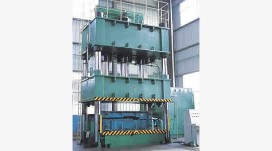
Basic requirements on a SMC press
Important is the right press force. We recommend around 1000 tons per square meter.
A parallelism control is advisable to protect mould, to safe material and to maintain a minimal clearance at die stops and to improve surface quality. It will help to maintain a uniform thickness reduce warpage and save material. The use of process control to maintain closing speed profile during flow of material is also basic.
For critical parts process control for maintaining pressure profile during material flow and material densification is needed. To de-mould the part air ejector capabilities build into press control system are very helpful.
It is a must for heating control system to achieve at least 160°C and it should be precise enough to maintain + - 2°C on surface.For Class A the parallelism control is also a must !
Using vacuum to reduce cavities and pinholes is nowadays state of the art for exterior automotive body panels. And for In Mould Coating capabilities build into press control system is often helpful.The moulding process
First optimize charge size and placement at break in and try out phase.
Use always the same charge pattern and placement. Use placement lines (cut in steel or laser) to indicate charge placement. Use always the same process parameters.
If SMC edges are dry cut them off and talk to your material supplier.
Use cutting machines rather than manual cutting or use templates to help in charge cutting. Make sure every cycle is identical in geometry (Charge size, weight and charge placement on mould). Make sure every cycle is identical in time (from placement of charge to mould close) and process parameters.
Maintain uniform mould surface temperature +-2°C.Compression moulding
Make the part come off easy at de-moulding. If this is not the case please check for ejector pins and undercuts. Check parallelism of ejector plate too.
Take off the part carefully and place part in cooling fixture to cool down in well defined position (nominal part contour, no clamping) and shape.Compression moulding cycle
When closing the press speed of upper mould half should be programmed to obtain a constant velocity of material’s flow front. If this is not possible or not desired we recommend a constant press speed of 8 mm/s. Immediately before densification starts change press control from velocity control mode to force control mode.
Typical velocity sequence:
t before mould hits material: 10mm/s
t when mould hits material: 8mm/s
t the next 3 mm
t the next 2 mm
t when 1 mm before final close set press control to force control mode.Low pressure and high pressure IMC
Powder coating is not used for painted automotive parts because of waviness but for exterior parts to decrease influence of weathering.
Low pressure IMC covers basically horizontal areas only.
Flash on edges and parallelism may cause problems.
High pressure IMC covers vertical areas as well .
IMC should act as a primer and should provide enough electrical conductivity for ESTA painting.Vacuum moulding for Class A parts
Vacuum moulding is applied for critical Class A body panels. When the mould is closed but top layer of material is not touched yet by the mould and the shear edges not engaged cavity surrounding is sealed and vacuum drawn.
Proper level of vacuum is 0,6 to 0,8 bar (0,4 to 0,2 bar of absolute pressure) . If vacuum is smaller pressure brownish areas may occur.
When required pressure is established (less then 3 seconds) the vacuum is switched off at final close of mould. All entrapped air is pulled out of tool and the risk of porosity is minimized.Home | News | Downloads | Contact Us
Copyright 2014 NingGuang Mould (c) All Rights Reserved.
Power by:imould

-
SMC Mould Blog
- 2014-5-19SMC Mould Advantage...
- 2014-5-17Treatment of SMC Mould products later...
LOCATIONS